A label is the sum of several interfaces
An 800G port means an aggregate line-side capacity, not a promise that every cable, host board, fiber plant, and software setting can carry the same workload. A 1.6T port doubles that aggregate label, but it can do so with more lanes, faster electrical lanes, faster optical wavelengths, or a different combination of those choices. Those designs move difficulty between the switch ASIC, package escape, module DSP, optical engine, connector, and fiber. A port-rate roadmap should therefore begin with an interface budget rather than a shipment forecast.
For parallel optics, a useful first equation is aggregate rate = lanes × rate per lane. Eight lanes at 100 Gb/s make 800 Gb/s; eight lanes at 200 Gb/s make 1.6 Tb/s. It is only an accounting identity. Ethernet or InfiniBand framing, FEC, encoding, breakouts, and the selected optical specification determine useful payload and interoperability. The OIF implementation-agreement library is the place to identify a named electrical or optical interface; it is not evidence that an arbitrary module is qualified in a particular switch.
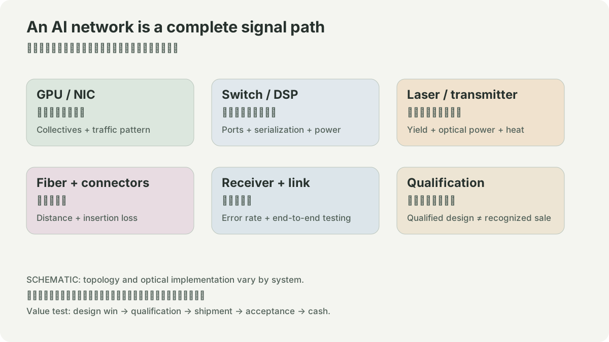
Follow the signal budget
The host sends a high-speed electrical signal from an ASIC through package traces, board traces, a connector, and a module. At each transition, attenuation, reflection, crosstalk, and noise reduce the opening of the received waveform. PAM4 carries two bits in each symbol by using four amplitude levels. That increases bit rate per symbol compared with two-level signaling, but makes the vertical margin smaller. A receiver needs equalization, error correction, and a specified channel-loss envelope. A faster lane is not simply a faster version of the old lane: it can demand a shorter electrical path or a different retiming arrangement.
Inside a pluggable optical module, the electrical lanes are recovered and conditioned, then drive laser modulation or a modulator. Light travels through fiber and is detected, amplified, and converted back into electrical lanes at the far end. The module datasheet must bind this chain to a reach, fiber type, connector, temperature range, and FEC assumptions. “800G” alone does not say whether it is a short multimode rack link, a single-mode data-center link, or a breakout topology.
NVIDIA’s current XDR documentation illustrates the distinction at a system boundary: it lists a 1.6T dual-port transceiver for a link to a pluggable XDR switch and an 800G single-port transceiver for a compute-side HCA in a CPO topology. That is a supported topology statement for that platform, not a general rule that 1.6T must always face a switch. Read the installation table alongside the relevant hardware manual before turning a port label into a bill of materials.
- 1ASIC SerDes
- 2board and connector loss
- 3module electrical receiver
- 4laser or modulator
- 5fiber
- 6optical receiver
- 7far-end SerDes
- 1rate target
- 2lane plan
- 3reach and fiber
- 4FEC and thermal test
- 5qualified link
Worked example: do not multiply the label twice
Suppose a leaf switch has 32 ports advertised at 800G. The maximum raw front-panel sum is 32 × 800 = 25.6 Tb/s. A proposal replaces every port with 1.6T. The new raw sum is 51.2 Tb/s, but it does not show that the ASIC has 51.2 Tb/s of forwarding capacity, that the uplink topology doubled, or that every server-facing NIC can terminate the new interface. Ask four questions in order: What is the ASIC radix and per-lane electrical interface? Which port splits are supported at this software and hardware revision? Which fiber type and maximum reach does the physical layout require? Which FEC counters, link-training events, temperature alarms, and retry behavior are accepted in burn-in?
If the old design used eight 100G lanes and the candidate uses eight 200G lanes, lane count has not changed but the signal-integrity challenge has moved. If it uses sixteen 100G lanes, front-panel density, fiber count, and connector choices change. Neither answer is automatically better; they create different manufacturing and operations constraints.
Limits, evidence, and lab
The transition changes the test plan as much as the throughput. Validate cold start, repeated insertion, link training, error counters under sustained traffic, thermal steady state, and a failed-link replacement procedure. Record exact switch, NIC, firmware, module revision, cable or fiber, FEC mode, and ambient condition. An error-free short demonstration cannot establish a production-row operating envelope.
AAOI’s 2025 10-K describes products spanning components, subassemblies, and transceivers in multiple end markets. It supports the observation that a supplier can participate in a higher-speed transition; it does not prove that every announced 1.6T interface becomes its revenue. Qualification, customer choice, yield, pricing, and capacity remain separate evidence.
Choose one proposed link and make an interface card: host and port mode; lane count and rate; form factor; optical specification; fiber and length; FEC setting; counters; temperature; and replacement procedure. Mark every unknown as unknown, then draw the cable path on a rack plan. This offline exercise is a design review, not a power or reach measurement.
NETWORK / HYPOTHETICAL INPUTS
Port labels and useful throughput differ.
An 800 Gb/s port multiplied by the selected useful fraction. This toy fraction combines idle time and overhead; it is not a measured link or a protocol model. Tail latency, topology, retries and collective algorithms need separate measurements. It cannot predict a supplier’s sales.
SOURCES
01YOUR NOTES