The module is a conversion chain
A pluggable transceiver is not “the optics” in isolation. It joins a host electrical channel to an optical channel and makes the reverse conversion at the other end. The chain contains electrical receivers and transmitters, control electronics, laser sources or an external-laser interface, modulators or directly modulated lasers, photodiodes, optical coupling, a package, firmware, and thermal paths. A fault reported as “the 800G module failed” may originate in a host channel, connector, marginal optical path, temperature condition, or the module itself.
At a high signaling rate, a DSP can recover a degraded electrical waveform with equalization, clock recovery, and coding-related processing. On transmit it can precondition the signal sent to the optical engine; on receive it can compensate for channel loss and recover symbols. This helps make an interface work across a specified channel, but consumes power, creates heat, and has defined latency. A linear driver or amplifier is a different choice: it may consume less power and add less processing, but depends on a tighter end-to-end signal budget. Do not call either approach universally superior without the specified reach, host loss, and error target.
Lasers, modulation, and detection
A transmitter needs a stable optical carrier and a way to encode electrical data onto it. In direct modulation the laser output itself is varied. In another design a laser supplies continuous light and a separate modulator changes it. A receiver uses a photodiode to convert arriving light back to current, followed by electrical amplification and recovery. Parallel optical lanes can carry an aggregate port rate across multiple fibers or wavelengths, depending on the selected specification.
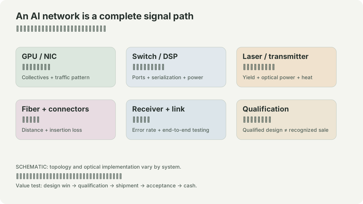
The component contract matters: wavelength plan, optical power and receiver limits, modulation quality, temperature behavior, connector cleanliness, and fiber attenuation all affect whether the detector can recover the signal. A laser’s nominal presence does not prove a link works. The full assembly needs manufacturing test and system qualification.
AAOI’s 2025 Form 10-K describes its light engines as combinations of lasers and photodiodes, sometimes with driver electronics or amplifiers and channel multiplexing components. That is useful because it separates laser components, subassemblies, and complete transceivers. It is an issuer description, not a comparative measurement of its modules against another supplier’s DSP or optics.
- 1host PAM4 lane
- 2electrical receiver and equalizer
- 3driver
- 4laser or modulator
- 5fiber
- 1fiber
- 2photodiode
- 3amplifier and DSP recovery
- 4host electrical lane
- 1power and heat
- 2monitoring
- 3alarms and qualification records
Worked example: separate an optical budget from a host-channel fault
An engineer sees intermittent corrected errors after a new module is inserted. The tempting story is “the laser is weak.” Instead create a matrix. Hold the switch port and fiber fixed while swapping a known-good module; hold the module fixed while moving to a known-good port; clean and inspect the connector; then compare diagnostic readings and counters before and after a thermal soak. If errors follow the module, its optical or electrical assembly is a candidate. If they follow the port, the host path or firmware configuration is a candidate. If they occur only after warming, the thermal budget is a candidate.
This has a limit: a working substitution does not identify a microscopic root cause, and changing several variables at once proves little. It does prevent an unsupported leap from a packet counter to a laser-supplier conclusion. Preserve timestamps, firmware, FEC mode, traffic pattern, and module identifiers under the site’s inventory policy.
Thermal and manufacturing limits
Power becomes heat inside a small removable package. Thermal resistance from electronics and optics to cage and airflow determines whether a room-temperature lab link remains within specification in a populated switch. Manufacturing adds gates: die yield, optical alignment, fiber attach, package choices, calibration, burn-in, and end-of-line test. More integration can reduce interfaces but can also make rework or isolation harder. The useful question is where test coverage sits and how a field replacement is handled.
NVIDIA describes LinkX transceivers as qualified with its networking systems. That is system-specific compatibility evidence. It cannot establish interoperability with every same-form-factor cage or a general performance ranking.
Lab: create a conversion and evidence map
Draw one selected link from ASIC pad to ASIC pad. Put a box around every electrical-to-optical or optical-to-electrical conversion, and label the specification owner, test instrument, observable counter, and replacement unit. Next to each claim write a source type: agreement, datasheet, compatibility list, lab measurement, or issuer filing. This offline exercise exposes missing evidence before a component name becomes a technical or commercial conclusion.
NETWORK / HYPOTHETICAL INPUTS
Port labels and useful throughput differ.
An 800 Gb/s port multiplied by the selected useful fraction. This toy fraction combines idle time and overhead; it is not a measured link or a protocol model. Tail latency, topology, retries and collective algorithms need separate measurements. It cannot predict a supplier’s sales.
SOURCES
01YOUR NOTES