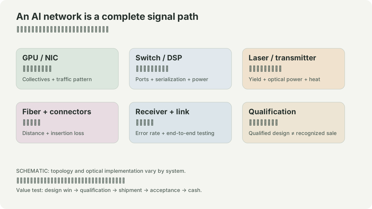
A backend network is a job-completion system
An AI backend network connects accelerators while a training or inference job repeatedly exchanges data. The useful unit of analysis is not an abstract “AI network,” but a path: a NIC emits an electrical signal, a leaf switch forwards it, a spine switch chooses another path, and a remote leaf and NIC receive it. The link may be passive copper, an active electrical cable, or a pair of optical transceivers joined by fiber. Each choice changes the number of ports, module endpoints, power sources, and field-replaceable parts.
Arista positions the 7800R4 as a modular universal spine for accelerated computing and specifies 800G and 400G density. Its published 36-port 800G line-card table lists 28.8 Tb/s of switching capacity and a 32 GB buffer for the cited cards. The product page also names EOS functions such as telemetry, EVPN-VXLAN, routing, and encryption. These specifications establish available platform attributes. They do not reveal which customer topology is deployed, how many ports are populated, or which optic vendor serves a system.
- 1accelerator -- NIC -- 800G leaf port
- 1 |\
- 1 | \ uplinks: fiber + two transceiver endpoints
- 1 | \
- 1 spine A spine B
- 1 | |
- 1 800G leaf ports -- NIC -- accelerators
- 1Control/operations: EOS telemetry
- 2counters, queue state, loss, link health
Count links before counting markets
In a two-tier Clos, every leaf normally has an uplink to each spine in the chosen design. Start with port arithmetic. Consider a toy fabric with eight leaves, four spines, and 32 accelerator-facing 800G ports on every leaf. Give each leaf four 800G uplinks, one to each spine. The fabric then has 8 × 32 = 256 accelerator-facing leaf ports and 8 × 4 = 32 leaf-to-spine links. If those 32 fabric links are optical, they require 32 × 2 = 64 transceiver endpoints before adding host-facing optics, spares, breakouts, or management ports.
This number is intentionally incomplete. A port can be unused, broken out, reserved for growth, or connected with a different medium. A chassis headline is capacity, not a port-population report. The correct next question is whether the topology, speed, distance, and operational policy are specified. Without them, converting a switch specification into a module or revenue estimate is speculation.
The hardware decisions behind a link
At 800G, the host electrical lanes, module form factor, fiber type, and reach determine which components qualify. Optical links add a DSP, drivers, lasers, photodiodes, connectors, and fiber path; the switch and module also have thermal budgets. Copper or AEC links can simplify short paths, but reach and cable routing constrain them. A deep-buffer spine may be selected for traffic behavior or routing scale, while a fixed system may be selected for a different density and footprint. Neither choice is a universal architecture rule.
The business consequence is layered. The switch platform vendor can capture chassis, line-card, EOS and support value. The optical ecosystem can capture module, DSP, laser, assembly, test, and fiber value. System integrators capture installation and acceptance work. A rise in port speed can change the mix among these layers, but it does not by itself say who receives the margin. Keep architecture, supplier qualification, shipments, and accounting recognition in separate rows of the research sheet.
Operate the fabric, do not merely draw it
Run a bounded experiment with one stated traffic pattern. First record the topology, port speed, link medium, distance, module temperature, FEC/error counters, queue occupancy, and congestion events. Establish an acceptance condition, such as no uncorrectable errors and a defined loss or latency threshold during a repeatable collective-like workload. Then change one variable: move a subset of leaf-spine links from one qualified optic to another, or alter the load-balancing policy. Compare the counters and job behavior before and after. If the outcome changes, report the condition that changed; do not attribute it automatically to “800G” or to the logo on the box.
Evidence boundary
Arista's official materials support the capabilities stated above, including the cited line-card density and platform features. They are not evidence for customer purchase orders, installed XPU counts, utilization, optical-module volumes, or supplier revenue. Treat vendor architecture as a map for questions. Answer deployment and financial questions only with a separately dated, source-specific record.
NETWORK / HYPOTHETICAL INPUTS
Port labels and useful throughput differ.
An 800 Gb/s port multiplied by the selected useful fraction. This toy fraction combines idle time and overhead; it is not a measured link or a protocol model. Tail latency, topology, retries and collective algorithms need separate measurements. It cannot predict a supplier’s sales.
SOURCES
01YOUR NOTES