Capacity becomes usable only through protected equipment
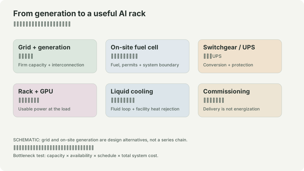
The utility service is the beginning of a data-center electrical path, not the end. A typical route includes service entrance equipment, switchgear, transformers, generators or alternate sources, transfer and paralleling equipment, UPS modules, distribution panels, busways, rack power distribution, and server supplies. DOE’s design guide describes this chain and notes efficiency improvements in double-conversion UPS systems (DOE guide). It is a design reference, not proof of a particular site’s topology.
Transformers change voltage and introduce rating, loss, cooling, protection, fault-duty, and delivery constraints. Switchgear isolates and protects faults but must be coordinated with upstream and downstream devices. UPS equipment bridges disturbances and converts power for critical loads, but its batteries, controls, bypass path, maintenance mode, and thermal environment are part of the reliability boundary. N+1 or 2N labels are shorthand; the single-line diagram and maintenance sequence decide what survives a failure.
DOE’s EMT model material discusses protection, transformer monitoring, and the way UPS continuity can affect protection design (DOE EMT models). That supports asking detailed dynamic questions, not copying a topology into every campus.
Commission the path, not only boxes
An installed transformer or UPS is not ready capacity. Verify factory tests, transport and installation, cable terminations, relay settings, grounding, arc-flash study, integrated-system test, generator/UPS transfer, bypass operation, and monitored alarms. Every change can affect the protection coordination study. A late breaker or control panel can block energization even when the transformer is present.
Use distinct capacity labels: nameplate rating, installed rating, commissioned rating, firm rating under the chosen redundancy rule, and delivered IT load. A 10 MW transformer does not imply 10 MW of rack load after cooling, conversion, reserve, and derating. A simple one-line drawing plus an acceptance-test register is more useful than a claimed campus capacity.
Exercise
Draw one electrical single-line diagram. For each device, record voltage, rating, normal source, alternate source, protective function, maintenance isolation, owner, and test evidence. Then remove one UPS or transformer in the model and state which loads remain supported. Do not assume the answer from the redundancy label.
Procurement is a risk only when it touches the critical path. Record supplier commitment, factory test date, transport, site readiness, installation, and energization separately. Replacing an unavailable device with a different rating or protection scheme requires engineering review; it is not merely a purchasing substitution. This makes long-lead equipment visible without inventing a generic delivery time.
Finally, keep facility power and IT capacity in one integrated acceptance test. A successful no-load electrical test does not prove that the system can maintain target compute through the selected fault and maintenance cases.
- 1utility or generator
- 2switchgear
- 3transformer
- 4UPS
- 5distribution
- 6rack
- 1relay settings and grounding
- 2fault isolation
- 3transfer test
- 4accepted load
- 1nameplate MW != commissioned MW != firm IT MW
POWER / HYPOTHETICAL INPUTS
IT power is only part of facility energy.
Annual energy = IT MW × PUE × 80% load factor × 8,760 hours. PUE = facility energy / IT energy. This planning example ignores seasonal changes and availability; it does not establish grid connection, fuel consumption or generation efficiency.
SOURCES
01YOUR NOTES