Density is heat that must cross interfaces
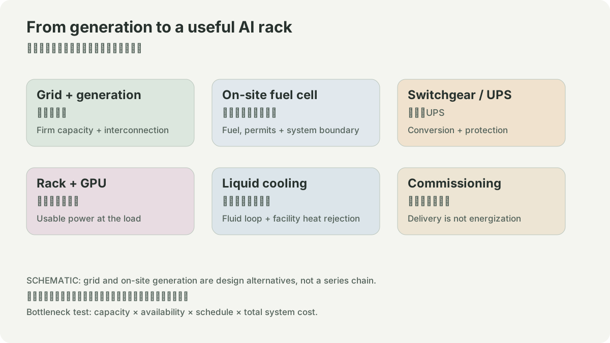
Higher rack power density turns electrical input into a thermal transport problem. The heat begins at chips, passes through package and cold plate or heat sink, enters air or liquid loops, then reaches a facility heat-rejection boundary. Direct-to-chip liquid cooling, rear-door heat exchangers, immersion, chilled water, and warm-water loops have different interface, service, leak, control, and maintenance demands. None is simply “more efficient” without a defined workload, climate, supply temperature, redundancy, and water boundary.
DOE’s demand work establishes a national reason to care about data-center electricity use, but it does not set a rack-density design target (DOE). The design guide identifies HVAC and electrical overhead as parts of the facility system (DOE guide). Site choices still need a thermal design and commissioning record.
Calculate heat, then list assumptions
Nearly all electrical input to IT eventually becomes heat in the facility. A hypothetical 80 kW rack at full load needs a heat-removal path for roughly that rate, but this does not determine flow, temperature rise, pump power, or chiller use. Those require coolant properties, inlet/outlet temperatures, pressure limits, distribution layout, and control response. Do not substitute a vendor’s maximum rack rating for measured application demand.
The key interfaces are server-to-CDU, CDU-to-building water, building loop-to-heat rejection, and controls-to-workload. Each has a leak-detection, isolation, water-quality, and maintenance plan. Liquid may reduce fan energy or enable higher density, but pumps, heat exchangers, water treatment, and redundancy remain loads and failure modes. Water consumption is also separate from water withdrawal and depends on the heat-rejection design.
Commission the failure states
Test loss of a pump, leak detection, CDU isolation, sensor failure, utility outage, generator mode, and a rapid workload change. Confirm how the rack throttles or shuts down, how alarms reach operators, and whether adjacent equipment shares a single point of failure. A cooling claim is operational only after this sequence is documented.
Exercise
For a fictional 10-rack pod, draw chip, rack, CDU, building-loop, and heat-rejection boundaries. Mark every meter and temperature sensor. Change one assumption—supply-water temperature or rack utilization—and describe which equipment and operating limit must be revisited.
Capacity planning should bind electrical and thermal assumptions together. Adding a higher-power server can require a different rack busway, CDU capacity, pump curve, heat exchanger, water-treatment regime, and maintenance method. Record the governing limit at each layer. The densest component is not necessarily the limiting component for the pod.
The operating runbook should therefore name the sensor thresholds, escalation owner, safe workload reduction, and return-to-service test. A thermal limit is only useful when operators can detect and act on it.
- 1chip heat
- 2cold plate or air path
- 3rack/CDU loop
- 4building loop
- 5heat rejection
- 1sensor and valve control
- 2alarm
- 3isolation or workload reduction
- 1rack density
- 2thermal design assumptions
- 3commissioned operating limit
POWER / HYPOTHETICAL INPUTS
IT power is only part of facility energy.
Annual energy = IT MW × PUE × 80% load factor × 8,760 hours. PUE = facility energy / IT energy. This planning example ignores seasonal changes and availability; it does not establish grid connection, fuel consumption or generation efficiency.
SOURCES
01YOUR NOTES